Designing a Virtual Campanile: Hardware
(Serving suggestion.)
Some initial thoughts about the hardware construction of the campanile.
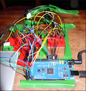
We are thinking about an eight-bell setup, with eight ringing posts, one for each bell. Each post has to be able to sense a ringing gesture, and to display the state of the bell (in other words, its position). Although physical bells are completely independent (I assume: is there any kind of physical interaction between them as they ring?), PEAL requires a central processing unit in order to display and animate ringing patterns. So: how independent are the ringing posts? How much of a brain does each one have?
It makes sense to base the design on the work for a project that is already in progress: Cyfnod by Eddie Ladd. (The design ideas in Cyfnod were a partial influence on PEAL.) Cyfnod makes use of laser-photodiode units in pairs – each pair forms a triggering beam – and each physical unit is equipped with a tri-colour super-bright LED cluster. (Hence, each beam system has two LED clusters.) The entire system is interfaced to an Arduino Mega processor board and controlled by MaxMSP via a custom serial protocol.
The lasers are 70-100mW red modules from OdicForce – they have a 3B safety rating, meaning that we have to take some precautions from a health-and-safety perspective, but they aren’t going to burn skin or set anything alight. (I know: I tried.) The LED clusters are microprocessor-controlled BlinkM units with onboard firmware to interface with I2C systems and/or run local autonomous colour animations. For the purposes of PEAL, we would be looking at something like the high intensity MaxM units – compatible with the basic BlinkMs but bigger and much brighter. (And, obviously, more expensive.)
The laser assemblies have onboard TTL pins for power switching – we use these because we want to be able to turn the beams on and off during the piece – and it’s obviously necessary to connect the photodiodes into the Arduino for sensing. In addition, there are potentially three channels into each LED cluster if we want full RGB control. This all adds up to a lot of channels.
The Arduino Mega provides sixteen analogue inputs – we only need eight, one per photodiode. The smaller Duemilanove board only has six analogue inputs. We could possibly treat (some of) the photodiodes as digital inputs with a bit of discrete logic – we only care about nominal “on” and “off” states – but that would imply calibration in hardware (not necessarily an issue, but perhaps tricky to do compared to software-based calibration and display).
The bigger problem is output. The BlinkM units talk I2C, which only needs two digital pins (plus power and ground), but the range of I2C is strictly limited – a figure of 20 metres has been quoted, and in practice we managed about 30 metres for two units on independent cables before failure. The range can be extended using buffering ICs, but we didn’t try this for Cyfnod – in fact, our “Plan Z” approach was to not use I2C at all in performance, but to preload a boot-up animation into each unit and simply gate the power to fire the animation. For PEAL, it’s possible that we could route an I2C bus between the posts and come in under 20 metres. Or, we could spring for the buffering ICs.
It’s also worth noting that the BlinkM MaxM units are quite expensive: £30 for a complete unit. (Most of that is the I2C microprocessor; the actual LED board is £8.)
If we drop I2C, then we need 24 analogue channels: RGB times eight. An Arduino Mega only has 14 PWM output pins (the Duemilanove has six.) Dropping the MaxM’s controller board (with onboard TTL power regulation) would involve replacing it with more discrete logic for power control.
So, what to do? Let’s look at some rough prices:
- Arduino Mega: £50
- Arduino Duemilanove: £20
- BlinkM MaxM with microcontroller: £30
- BlinkM MaxM LED board only: £8
(We’re assuming that the basic MaxM board is the best way to get a collection of three super-bright LEDs.) The Duemilanove doesn’t have enough analogue inputs for the photodiodes (assuming we want to keep them analogue), which suggests we want a Mega or a pair of Dues.
So, sufficient Arduino pinage and MaxM I2C everywhere: somewhere in the £250-300 region.
Go for the MaxM LEDs only – that’s £64 – and we’d need four Dues (add £80) or two Megas (add £100). So, PWM output to the LEDs saves about £100, at the expense of much more wiring (RGB to every post independently, rather than a shared two-wire bus) and extra circuitry for the LEDs’ power supply.
(As an aside, we’ve found the BlinkMs to be delicate: out of a batch of 15 or so, three had a sporadic or totally nonfunctional colour channel, and we managed to blow two completely – and we also killed a MaxM processor we bought for evaluation – so we should budget for some predicted attrition with any I2C hardware.)
The remaining question: how to run two (or more!) Arduinos in the same installation? I assume the answer is pretty simple. Presumably it’s possible to hang them off a Mac’s USB port as multiple virtual serial devices – and, at worst, add some auto-ident sequence so that the host software can work out which is which in case the port allocation is dynamic. Alternatively, we could network them via Ethernet (the Ethernet shields are £30 a pop)… or perhaps just link two boards together via I2C? 🙂
[…] configuration as the full-scale installation (Nick’s posted a fairly thorough overview of the electronics design for PEAL on our development blog) but replacing the lasers with simple buttons or preferably Nintendo […]
May 30th, 2010 at 9:04 am[…] benefit, especially as that approach would require multiple communicating boards. (More thoughts at http://blog.monomatic.net/?p=106.) Posted July 21st, […]
January 7th, 2011 at 11:00 am